Rotary Kilns: How To Select The Right One

Although carbon regeneration can be achieved via a multitude of technologies, the most cost effective both in capital expenditure and ongoing spares is using an indirect fired horizontal rotary kiln.
Indirect fired rotary kilns have been used for carbon reactivation and regeneration for over half a century. The fundamental design of the rotary kiln has changed little in that time, but the process logic, heating and control technology has evolved exponentially. It is therefore very important to understand what each rotary kiln manufacturer/supplier is offering and whether that technology is fit for purpose.
Things To Consider When Selecting an
Indirect Fired Horizontal Rotary Kiln
Rotary Kiln Size
The size of a carbon regeneration kiln has a direct correlation with the cost of that unit. The larger the piece of equipment is, the more material is used and anecdotally – more man hours involved in the manufacturing of it. However, a bigger kiln does not necessarily mean a better kiln.
In a rotary kiln, the diameter and length of the heat tube is critical to process considerations. To effectively achieve carbon reactivation, it is widely held that the carbon must be exposed to a water vapour atmosphere for a minimum of 10 minutes at or above 750°C. This allows for the pyrolysis of the entrained foulants within the carbon and for those foulants to be oxidised or removed from the kiln via the gas stream. The carbon is therefore ‘cleansed’ of the foulants and reactivation has occurred.
For the carbon to achieve the temperature and time profile in the water vapour environment as described above, the carbon bed within the rotating heat tube must be kept quite shallow. If the heat tube diameter is too small for the required throughput, then the carbon bed will be too deep. This means that the carbon has less time exposed to the required reactive environment and that heat transfer may not uniformly be achieved into the carbon bed, thus reactivation levels will suffer. Conversely if the heat tube diameter is too large, the carbon bed depth is very shallow and the carbon has greater exposure to the required environment and better heat transfer, so carbon reactivation is achieved far more easily. However, the difference in capital cost for the larger rotary kiln and higher ongoing running cost to heat what is essentially an empty space in the heat tube needs to be taken into consideration.
Carbon Transport & Storage
Carbon can be transported in many ways. The two most common ways are dry in large ‘bulky’ bags, or via a medium such as water. It is important to understand the nature of the carbon transport to the carbon regeneration kiln as the transport method will have an impact on how the kiln reactivates that carbon!
It is critical to ensure that the carbon being fed into the rotary kiln is no more than 40% w/w and preferably no less than 5% w/w. Achieving the correct carbon moisture content ensures that sufficient steam is generated from the entrained moisture from the spent carbon being fed into the kiln without taking too much thermal load at the feed end of the unit. It will also ensure that there is no damage to the heat tube.
Dry Carbon
As mentioned earlier, for the carbon reactivation to occur the carbon must be exposed to a water vapour environment within the heat tube for a minimum of 10 minutes. If the carbon is transported to the rotary kiln in a dry format, then there is a requirement for steam to be ‘injected’ into the heat tube to artificially create the water vapour environment. This can be easily achieved from either the feed end (for co-current steam flow) or from the discharge end (for counter current steam flow).
The steam also creates an inert atmosphere within the heat tube and enables the carbon to achieve the required reactivation temperature profile without combusting.
Wet Carbon
If the spent carbon is transported to the carbon regeneration kiln via water, then the carbon must be de-watered first. This is where carbon sits in a holding hopper and most of the free water is removed from the carbon via a de-watering screen prior to the carbon entering the kiln. The carbon dewatering stage is quite critical to the rotary kilns efficiency and ability to reactivate the spent carbon
If the carbon is introduced to the hot internal space of the rotating heat tube prior to releasing most of its entrained moisture, the rotary kiln will use an excessive amount of its thermal energy trying to dry the carbon and flash off that moisture into steam. Additionally, the water coming into the rotary kiln can cause pressure differentials within the feed end of the heat tube and thermal shock which can cause deformation of the heat tube shell. This heat tube deformation could cause the heat tube to lose alignment and in severe cases, lose structural integrity.
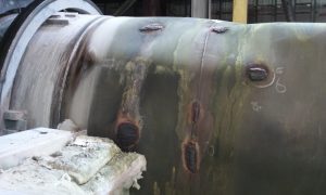
Image 1 – Carbon regeneration kiln heat tube deformation from saturated carbon feed.
It is critical to ensure that the carbon being fed into the rotary kiln is no more than 40% w/w and preferably no less than 5% w/w. Achieving the correct carbon moisture content ensures that sufficient steam is generated from the entrained moisture from the spent carbon being fed into the kiln without taking too much thermal load at the feed end of the unit. It will also ensure that there is no damage to the heat tube.
Feed System
The two common types of feed systems into carbon regeneration kilns are the feed screw (auger) and the vibrating tube.
Feed Screw
The feed screw is by far the most common mechanical feed system for delivering product into a rotary kiln. The feed screw is very effective for several practical reasons:
- Whilst there is spent activated carbon located between the flights of a feed screw, this fractional fill of product creates a very effective barrier against oxygen ingress into the heat tube whilst at temperature.
- With a VSD controlled motor, the feed screw will allow a far more accurate feed rate calculation based on the need to increase or decrease volume of product into the rotary kiln; and
- Feed screw augers are very simple in design and easy to maintain and repair.
1). The first option is the incline feed screw that transports the carbon up on an angle into the heat tube:
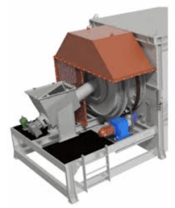
Image 2 – Incline feed screw. Photo credit: KEMIX.
The incline on the feed screw allows the carbon to continue to release water during the feed phase and gravity will propel the free moisture to the lowest point of the feed screw assembly where the water is expected to drain. As this is the case, gravity also pushes the carbon against the opposing force which are the feed screw flights forcing the carbon up the incline.
As the feed screw is a mechanical feed mechanism, this will cause a certain amount of structural damage to the carbon as it feeds up into the heat tube. This is a very minor consideration, the difference in carbon attrition in this style of feed screw versus a horizontal feed screw is negligible.
2). The second option is the horizontal feed screw:
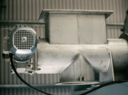
Image 3 – Horizontal feed screw
The horizontal feed screw option works in the same way as the incline feed screw. The only real difference is that any free water in the carbon is expected to exit from the filter arrangement located on the underside of the feed screw housing (as seen in image 3). As the feed screw transports the carbon through the housing and into the heat tube, the carbon will compress slightly and assist in forcing free moisture out of the feed passage.
Vibrating Tube
The second and less common style of feed system for rotary kilns is the vibrating tube feeder.
The vibrating tube feeder consists of a suitably sized metallic cylinder that is oscillated at a set frequency by vibrating motors to encourage carbon movement from the hopper end of the cylinder forward and into the heat tube. The logic behind this style of feed option is that the vibrations do not mechanically damage the carbon as the carbon ‘jumps’ forward with the movement of the cylinder that the carbon is located within.
There are however some significant flaws in the process side of using a vibrating tube feeder:
- It is not possible to accurately increase or decrease feed rates by modifying the vibration frequency of the vibrating motors. A 5% change in vibration frequency does not linearly equate to a 5% increase/decrease in feed;
- Even without changing the frequency of the vibrating motors, the feed rate can change from batch to batch quite substantially just through simple things that may enhance or dampen the vibrations such as:
- Water content on the carbon being either higher or lower; and
- Foulants being present in the carbon feed such as sand or ceramic matter.
- The vibrating tube can also be subject to blockages where foulants in the carbon feed can adhere to the walls of the tube and reduce the natural carbon flow.
Seals
Seals on most rotary kilns are either a mixture of high temperature material seals (or gland packing) and mechanical seals, or just mechanical seal.
Material Seal
The material seal is most often found at the feed end and the discharge end of the rotary kiln combustion chamber. The idea of the material seal is to encompass the diameter of the heat tube and accommodate the expansion and contraction of the heat tube whilst the tube is rotating.
Material seals are commonly deployed in the task of keeping combustion gases within the combustion chamber. To achieve this, the material seal must meet some robust requirements:
- The seal must be durable enough to maintain seal integrity against high velocity and high temperature combustion gases. Having a multiple layer seal provides extra rigidity and ability to use multiple high temperature materials for greater seal longevity.
- The seal must be able to provide for wear against the heat tube as it expands and contracts with heat whilst rotating. Using a material that has both high temperature rating and stainless-steel mesh for wear protection is ideal; and
- The seal must be easily removable and replaceable during routine maintenance in the field.
Mechanical Seal
The most common style of mechanical seal is the leaf seal. The leaf seal consists of numerous flexible metal plates that overlap each other and flex to apply additional downward pressure onto the heat tube as the tube expands with heat, and then relax and regain their original shape and position as the tube cools and contracts.
The mechanical leaf seal generally comes in one of two configurations. A single leaf seal and a double leaf seal. The final seal is where the mechanical seal comprises of an inner and outer overlapping spring leaf configuration with a high temperature material layer sandwiched between the spring steel leaf layers.
The benefits of using a mechanical seal on a rotary kiln are many. The primary benefit is that the mechanical seal can cope with the high temperatures that kilns tend to operate at and generally last longer than a material seal. Additionally, the double leaf seal provides for multiple layers of sealing over a variety of mediums, but still provides the flexibility of being designed and used on rotary kilns of any size.
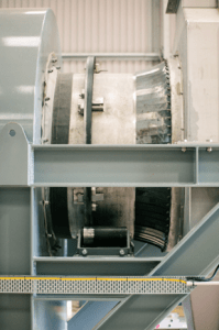 Image 4 – High temperature material seal (seen on the left) and the mechanical leaf seal (seen on the right).
Control Logic, Communications, & System Integration
Although the mechanical components of Carbon Regeneration kilns have not changed significantly in the past 6 decades, the systems that run and control them have. With the introduction of the internet, TCP/IP communications and networked components, rotary kilns today can be managed more finitely, have control logic modified more easily, and capture more data than at any time previously.
Communications networks and protocols change from site to site and can even change from process to process within the same site. It is for this reason that communications flexibility should be a driving factor behind equipment selection. Having the ability to communicate via Modbus, Profibus and TCP/IP would be an advantage. Having the rotary kiln supplier being technology agnostic for items like the PLC, HMI and other communicable devices is also very attractive.
Up until recent years, the more sophisticated vendors have considered offering remote access for P&ID loop changes or programming changes to their equipment as an add on option. Although there are still few in this space offering these options, there are now more agile rotary kiln suppliers that are offering remote access capabilities on their equipment as standard. By utilising this function, the end user can have necessary programming changes made to the equipment quickly and without having a vendor technician attend site. This saves time and unnecessary cost both in labour fees, but also in unrealised productivity.
Heating
The ability of a rotary kiln to achieve its required setpoint temperature in a pre-determined timeframe and maintain that setpoint is the essence of its core function. If the kiln is unable to achieve or maintain its setpoint temperature, then there is something critically wrong with either the equipment or the process.
An indirectly heated horizontal carbon regeneration kiln can be heated through a variety of sources. The most common form of heating comes through the combustion of fossil fuels by way of one or more single / multiple stage burners. The burner ignites and combusts the fossil fuel source and the fuel is mixed with a set level of excess oxygen to create a stable and clean flame that fires into the rotary kiln combustion chamber. The combustion chamber creates an oven effect and as the heat tube rotates within the combustion chamber, the heat energy transfers via convection through the heat tube skin and into the carbon.
Consideration needs to be given to standards relevant to the country that the rotary kiln will be operating in. Australian kilns that are heated through combustion of diesel are not subject to statutory licencing or inspection. However, any unit that is heated using the combustion of LPG or Natural Gas is classified as a Type B gas appliance and this equipment is subject to very strict requirements:
- The kiln must be passed as acceptable by the Worksafe authority for which it is being installed.
- Commissioning gas needs to be applied for and approved prior to the Type B gas appliance being commissioned; and
- A certified gas inspector must sign off on the installation and equipment prior to approving the kiln for ongoing approved consumer gas and allowing the unit to be operated by trained personnel.
Part of the formal Type B gas appliance approval is based on how the burners and fuel line (sometimes called the gas train) are set up and the respective components that make up the fuel line. If the Carbon Regeneration Kiln has been built internationally for use in Australia, consideration needs to be taken in what is needed to ensure that the gas train is compliant with Australian standards.
Additionally, the rotary kilns’ control system, safety interlocks and process parameters are also scrutinised during the formal Type B gas appliance approval. It is necessary to ensure that the electrical control cabinet is constructed to meet Australian standards and that all the relevant safety interlocks are incorporated into the final product and that they are tested to work prior to shipping the unit to Australia.
You can read more about Type B Gas appliance guidelines here.
In some projects the most cost-effective way of creating heat within the combustion chamber is electrically. These rotary kilns generally have element trays that sit beneath the rotating heat tube. It is very important to make sure that the electric elements used in these rotary kilns are fit for purpose. For example, a rotary kiln located in Indonesia and using electrically powered elements was found to lose a significant number of elements through shorting by way of condensation build up in the heating chamber. The kiln OEM had failed to consider the relative humidity of the tropics and did not allow for forced air flow to either suck or push the moisture rich air from the area where the elements were located. As the elements were prone to this type of damage, the client site spent more than $50,000 each year in element replacement.
Discharge
The discharge end of a Carbon Regeneration kiln is a critical area of the unit and can sometimes be the most prone for mechanical and structural failure. Depending on the design of the rotary kiln, the discharge chamber of is often the item of the unit that is most overlooked from a maintenance perspective.
Water Cooled Discharge Chamber
The water-cooled discharge chamber is most often a double jacketed type. This style of discharge chamber has the water pass between the external jacket (exposed to the atmosphere) and the internal jacket (internal to the discharge chamber).
As the name suggests, the main function of the water-cooled discharge chamber is to provide some cooling of the carbon before it exits the cooling zone and is discharged from the kiln. Although the idea has merit, most carbon regeneration kiln discharge chambers are only cooled by ambient process water and do not hold the carbon for enough time for any cooling to take effect.
Another issue that the water-cooled discharge chamber encounters is the metal fatigue of the inner and outer jacket. As the discharge chamber expands and contracts with the heat from the rotary kiln, micro fissures tend to emerge along the weld lines and suddenly there is water making its way into the discharge chamber. The water ingress into the discharge chamber itself is not a critical issue generally due to the small amounts of water that are forced through these small cracks, but this does lead to a much larger issue
As the carbon is being regenerated within the heat tube. A volume of foulants that are driven off the carbon are caught in the gas stream and are carried through the rest of the heat tube and into the discharge chamber. The lighter molecules stay in the gas stream and exit the kiln. However, heavier molecules once in the cooler environment of the discharge chamber can change phase from gas to liquid and tend to amass within the discharge chamber interior. If these molecules are in close proximity of water pushing into the discharge chamber, then the discharge chamber has more steam being generated within it which creates a further cooling effect and in turn a greater volume of molecules change phase. After time, these liquids (loosely resembling a sticky tar like substance) are of sufficient quantity to start capturing loose carbon within the discharge chamber.
Activated carbon is a product that when captured in state, tends to bridge and when carbon bridges, it often causes blockages. These carbon blockages can go from quite mild to complete blockages within a very short period.
In some rotary kiln designs, the steam pipe that takes the steam from the discharge chamber to the stack, is internal to the kiln cover. As the lighter molecules and carbon fines are carried along with the steam, the molecules change phase and begin lining the internal surface of the steam pipe. The carbon fines then begin sticking to the internal pipe surface.
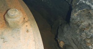
Image 5 – Significant tar and carbon build-up inside a water-cooled discharge chamber.
Dry (Hot) Discharge Chamber
The dry discharge chamber is most often a single skin unit that runs hot at the end of the carbon regeneration kiln. This style of discharge chamber is a much simpler design than the double jacket and very little generally goes wrong with it.
As the dry discharge chamber does not use water, the chamber internals and externals are at roughly the same temperature as the carbon coming out of the heat tube. Due to the increased skin temperature of the chamber, there is additional need for external guarding against someone touching it. However, the added benefit of the chamber internal wall being hotter is that any of the residue that may cool into a liquid within the cooler chamber environment is generally still too hot to congeal on the chamber inner wall. The constant hotter environment inside the discharge chamber generally finds these tarry type liquids continue to run down the walls of the chamber and exit the kiln with the carbon.
Mobile Discharge Chamber
Where a fixed discharge chamber on a rotary kiln is designed to accommodate for the radial and axial expansion of the rotating heat tube as it gets hotter, the mobile discharge chamber only accommodates for the radial expansion. As the heat tube begins to expand axially (gets longer), the mobile discharge chamber ‘moves’ horizontal to the kiln to accommodate.
The most common form of mobile discharge chamber is set on rollers that run along short tracks horizontally away from the kiln. As the heat tube expands, the discharge chamber is gradually pushed along the tracks until the heat tube is at full expansion. Conversely as the kiln begins to cool down and the heat tube starts to contract, a return system engages (most commonly using springs) to pull the discharge chamber back slowly and gradually into its starting position.
As with any mechanical item, the mobile discharge chamber requires maintenance to reduce wear and failure. In aggressive environments such as mine sites, particles large enough to cause fouling of the tracks are common. If the tracks that the chamber roll along are not kept clean of obstructions and lubrication maintained in both the rollers and on the tracks, then there is a high chance of the discharge chamber becoming immobilised. When this occurs, there is also a chance of damage to the end of the heat tube as it pushes against the discharge chamber internals.
Common Wall Between Discharge Chamber & Combustion Chamber
A popular and common carbon regeneration kiln design is where the combustion (heating) chamber and the discharge chamber share a common wall. This rotary kiln design is one that can cause more kiln downtime and damage than any other mechanical failure. This is due to inability of any kiln manufacturer yet being able to design an effective sealing arrangement that can adequately withstand the temperatures, foulants, carbon and gases found inside the discharge chamber.
When the internals of the discharge chamber are sufficiently fouled to create carbon bridging, the carbon is unable to exit the kiln as normal. In this situation, the carbon exits the heat tube at a temperature of around 400°C. The carbon cannot exit the kiln due to the bridging and therefore continues to build up inside the discharge chamber.
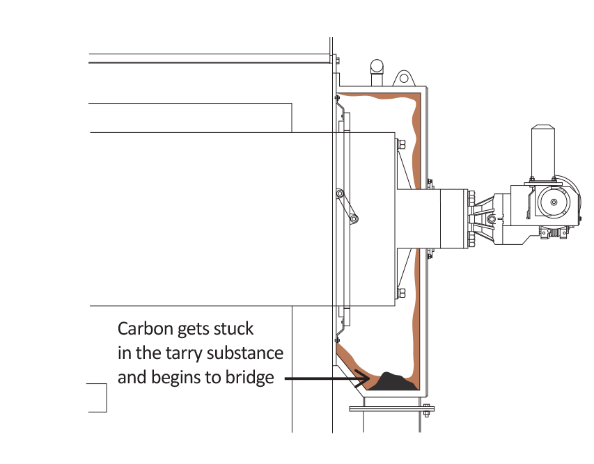
Image 6 – Tar and carbon build-up inside a water-cooled discharge chamber.
Whilst the carbon builds up within the discharge chamber, the void is filled, and finally hot carbon encounters the seal that encircles the heat tube and separates the two chambers. Before long, the carbon breaches this seal and flows from the discharge chamber into the combustion chamber.
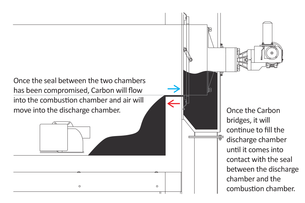
Image 7 – Hot carbon breaching the seal between the combustion chamber and discharge chamber.
As carbon discharge is not generally monitored for volume, the carbon incursion into the combustion chamber can continue for a period until the combustion chamber has a deep layer of carbon in it. The danger with this is that carbon is a combustible product and as the carbon continues to migrate into the combustion chamber, there is more fuel that can burn in an uncontrolled environment.
Image 8 – Carbon burning in a rotary kiln combustion chamber 3 days after last kiln run.
When carbon ignites and burns in a rotary kilns combustion chamber, it is usually noticed through uncontrolled heat spikes on the kiln temperature probes. Additional signs are black smoke coming from the stack and hot spots evident on the kiln combustion chamber outer shell. The fire will destroy the combustion chamber inner lining which will need to be replaced for thermal efficiency to be returned. There is also the potential for damage to the burner heads and internal baffles (if present).
Equally important and damaging is oxygen entering the discharge chamber from the combustion chamber. Once the seal between the discharge chamber and combustion chamber is breached by the hot carbon, the oxygen rich combustion gases from the burners can push in the opposite direction to the carbon and enter the discharge chamber. Once the oxygen is in the discharge chamber there is now all the ingredients for carbon combustion in the discharge chamber and heat tube.
The cost to repair the carbon regeneration kiln after such an incident is financially high, but more costly in kiln downtime.
Service & Maintenance
Although rotary kilns are not mechanically sophisticated, it is important to provide regular maintenance to ensure optimum performance. When selecting a kiln vendor, ensure that they have an experienced and available service and maintenance team to assist with both planned and unplanned equipment shuts.
It is important to understand the depth of knowledge that the OEM service team have and how those members can educate the on-site maintenance team in the obvious as well as nuanced terms of each piece of equipment. By better learning and understanding ‘field hacks’ that the OEM service team have developed over years of service experience, the on-site maintenance team will be able to more easily and rapidly investigate and solve common problems.
Having an OEM that supports the equipment remotely is also incredibly valuable from both a production and efficiency perspective. If the OEM service team can assist the site maintenance team via either telephone, video call or remote equipment login (or all of these), then the ability to rectify a fault more efficiently is far more likely to occur.
Spare Parts
In recent years, supply chain constraints have become apparent due to the COVID-19 pandemic. With international freight reducing in volume and increasing in cost, it is important to consider access to spare parts as well as what warehouse bin holding levels are required moving forward.
As many carbon regeneration kilns are located remotely and transport of parts to site takes time, it is worthwhile considering where the spare parts are being supplied from. In a perfect world, all spare parts on a rotary kiln are off the shelf items and can be procured easily from multiple vendors. Unfortunately, this is not the case, and some items (mostly fabricated spare parts like heat tubes) can only be manufactured in one or two places. Therefore, forward planning is needed to ensure that all critical spares are on site when needed and there is no need to wait many weeks or months for items to be sent by air or sea.
Geographical Representation
Having a vendor in the same geographical region as you will certainly make procurement of equipment, service, and supply of spare parts far easier and quicker. As importantly though, having a local vendor ensures that all rotary kilns are designed, manufactured, and delivered complying to all local standards.
Additionally, geographical representation is important for the supply of spare parts and service expertise. Having a vendor that can expedite essential items and expertise to site through country or regional warehouses located closer to site will reduce lead time, freight, and equipment downtime.
Heat Systems Products
Heat Systems Carbon Regeneration Kilns are ideal for all Carbon Reactivation & Recovery needs and designed with three factors in mind.
Carbon Regeneration Kilns
Heat Systems offer gold furnaces in a range of sizes designed for efficient, high-temperature use with minimal maintenance.
Smelting Furnaces
Heat Systems offer an extensive range of quality heat transfer oils that are cleaner running, longer lasting thermal fluids.
Heat Transfer Oils
Heat Systems designs and manufactures complete thermal oil elution heaters or direct eluate heating packages to suit your process requirements.
Elution Heaters
The Heat Systems screw conveyors are simple, robust and flexible, and are often employed to adjust the temperature of a solid material prior to storage or further processing.
Screw Conveyors
HEAT Systems don’t just supply you with off the shelf items, we manufacture them with you in mind. This gives us an intrinsic knowledge of the thermal heaters and equipment we supply.